Download Our App

Electromagnetic Induction notes for DU students
ELECTROMAGNETIC INDUCTION (Chapter 29)
INDUCTANCE (Chapter 30) below
KEY TERMS: induced current, induced emf, Faraday's law of induction, Lenz's law, motional emf, induced electric field, Maxwell's equations.
 |
|
|
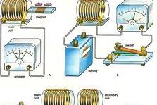
Fig. 29.1 Induction of a current in a coil of wire
|
|
Whenever there is a change in the number of magnetic field lines passing through a loop of wire a voltage (or emf) is generated (or induced) in the loop of wire. This is how an electric generator works. The phenomenon is known as electromagnetic induction and is explained by
Faraday's law of induction:
e = -- dF / dt
where F is the magnetic flux given by the closed integral of the dot product B 0 dA.
 |
According to Faraday's law, |
|
Fig. 29.2 Coil in a uniform constant magnetic field
|
 |
|
|
Fig. 29.3 Magnetic flux (F)
|
 |
According to Faraday's law, as the
If the strength decreases there will also
Lenz's law indicates the polarity |
|
Fig. 29.5 Coil in an increasing magnetic field
|
 |
|
|
Fig. 29.6 Changing magnetic flux induces current (recall I = V / R)
|
 |
|
|
Fig. 29.8 Alternator (AC generator)
|
In an AC electric generator, or alternator, the flux through the loops of wire (wound on the armature) changes, and therefore according to Faraday's law there will be an emf induced in the loops of wire.
This induced emf causes a current to flow in the loops.
 |
|
|
Fig. 29.10 DC generator
|
In a DC generator the direction of the induced current in the loops must be changed every one-half
turn of the generator shaft. This is done with split rings on the rotating armature contacting the
stationary "brushes" which are in turn connected to the wires coming out of the generator.
There is another way to see how a current is set up in the loop.
The electric force equation F = q v x B and the right hand rule indicate there is a force on the charges (electrons) in the purple bar that is moving with velocity v.
 |
|
|
Fig. 29.11Slidewire generator |
 |
|
|
Fig. 29.12 Induced current (I) causes a force F = I L x B to be exerted on the bar.
This force is in the direction opposite to the velocity v. |
 |
|
|
Fig. 29.13 Lenz's law describes the tendency of nature to resist any
change in magnetic flux passing through a loop of wire. Changes in flux can be canceled by inducing a magnetic field in the appropriate direction. |
 |
|
|
Fig. 29.14 Induced currents caused by changes in magnetic flux
|
 |
|
|
Fig. 29.15 (a) Induced emf in rod, (b) induced current in wire loop
|
 |
|
|
Fig. 29.17 Solenoid with changing current.
The galvanometer G will record the presence of an induced emf in the loop of wire caused by the change in flux passing through the loop. |
 |
|
|
Fig. 29.19 Eddy currents
|
 |
|
|
Fig. 29.20 Metal detector
|
|
Maxwell's Equations (section 29.7) will be covered later in Chapter 32 "Electromagnetic Waves."
Maxwell's four equations 1. Gauss's Law for electric fields 2. Gauss's Law formagnetic fields, 3. Faraday's Law, and 4. Ampere's Law as modified by Maxwell predict the existence of electromagnetic waves capable of propagating through empty space at the speed of light, which is an electromagnetic wave. |
|
|
|
 |
|
|
Fig. 29.31 Lenz's law
|
.JPG) |
|
|
Fig. 29.33 Lenz's law (Exercise 29.17)
|
.JPG) |
|
|
Fig. 29.34 Lenz's law (Exercise 29.18)
|
.JPG) |
|
|
Fig. 29.37 Lenz's law (Exercise 29.21)
|
By Ashish Kumar Yogi

Campus News & Events
-
 Study materialColleges are sharing lecture notes, study material, file, assignment etc.
 -
 Educational videosCollege student sharing a great video to help peers study.
 -
 Previous Year PapersAccess previous year papers for various courses.
 -
 Clarify DoubtsAsk any study related doubt and get answered by college students and faculty.
Info. update by students of the respective college only.


